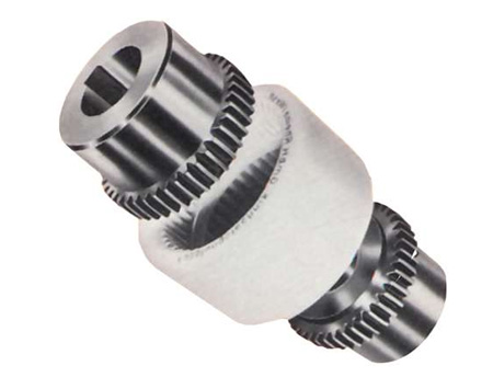
Plum-shaped elastic coupling
Diaphragm coupling
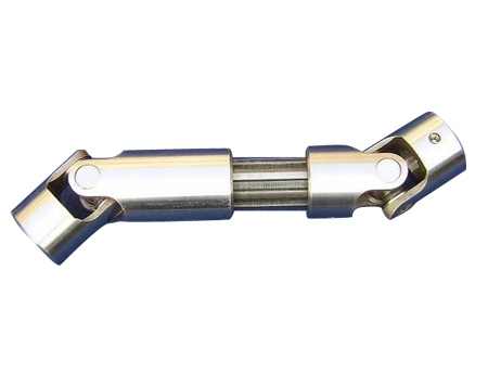
Universal coupling
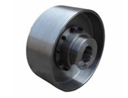
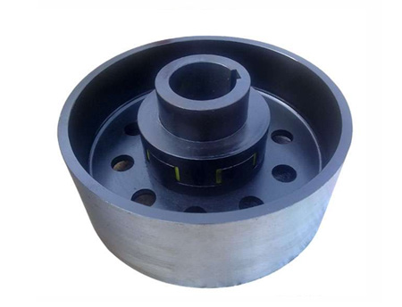
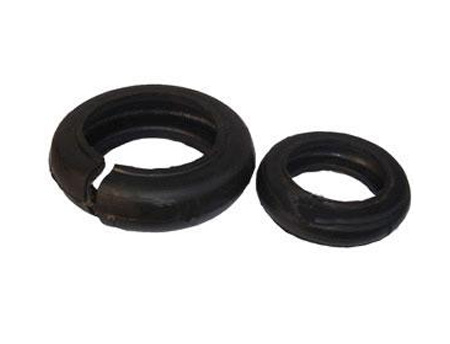
Tyre coupling
Slider coupling
Rigid coupling
Star-shaped (shaped) elastic coupling
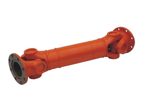
Drum gear coupling
Elastic sleeve pin coupling
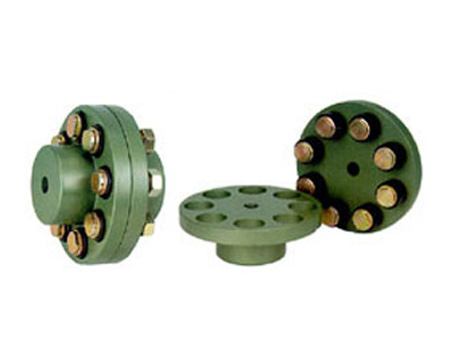
Elastic pin coupling
Elastic pin gear coupling
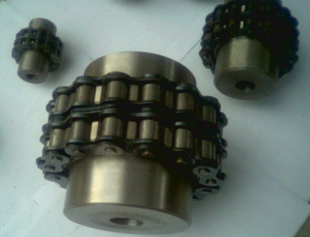
Roller chain coupling
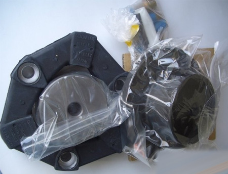
Various coupling accessories
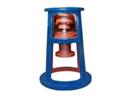
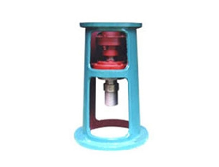
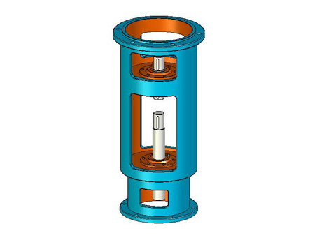
Water pump coupling
Expansion sleeve
Rack series
Website: www.rigid-shaft-coupling.xyz
Address: Xihuan Industrial Zone, Botou City, Hebei Province
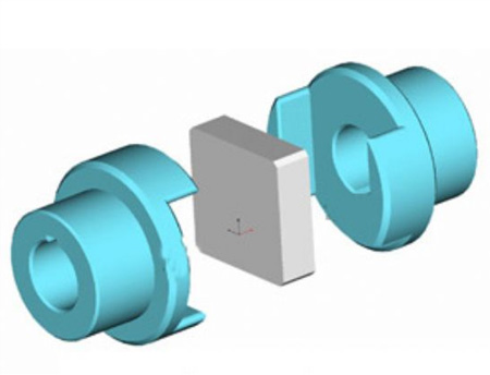
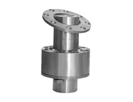
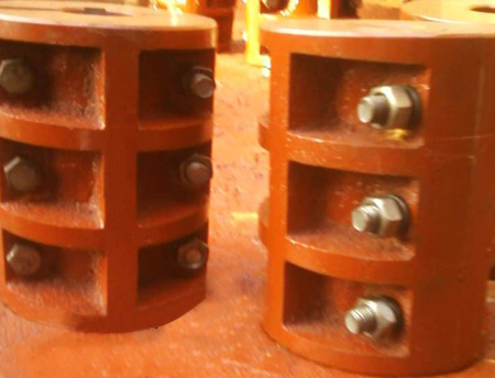
Slider coupling
Slider couplingSimilar to the cross slide coupling structure, the difference is that the middle cross slide is a square slide, and the middle slide is used to slide in the corresponding radial grooves on the end faces of the half couplings on both sides to realize the two halves coupling.器连接。 Connectors.
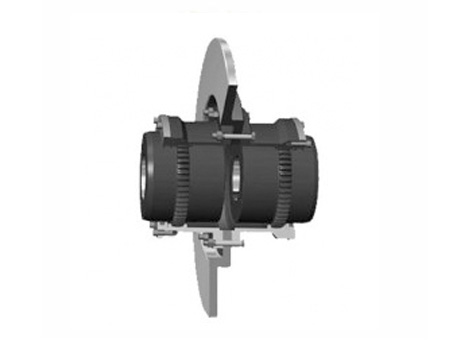
The material of the sliding block coupling parts can be 45 steel, and the working surface needs to be heat treated to improve its hardness; Q275 steel can also be used when the requirements are lower, without heat treatment.In order to reduce friction and wear, oil should be injected from the oil hole of the middle plate for lubrication during use.Because the half-coupling and the intermediate disc form a moving pair and cannot rotate relative to each other, the angular velocity of the driving shaft and the driven shaft should be equal.However, when working with relative displacement between the two shafts, the middle disk will generate a large centrifugal force, which will increase the dynamic load and wear.Therefore, pay attention to the working speed not greater than the specified value when selecting.This kind of coupling is generally used for speed n<250r/min, the rigidity of the shaft is relatively large, and there is no severe impact.
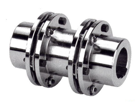
The central sliding block is connected with the shaft sleeves on both sides by 90° oppositely distributed clamping grooves on both sides, so as to achieve the purpose of transmitting torque.The center sliding block and the shaft sleeve are matched with a slight pressure, which enables the coupling to run with zero clearance during the operation of the equipment.As the use time increases, the slider may lose its recoilless function due to wear. However, the center slider is not expensive and is easy to replace. After replacement, it can still exert its original performance.
Slider couplings are often used in common motors, and can also be used to connect servo motors on individual occasions. The relative displacement can be corrected by the sliding of the center slider during use.Because the resistance to the relative displacement is the friction between the slider and the sleeve, the bearing load between them will not increase due to the increase in the relative displacement.
|
model
|
Nominal torque Tn(Nm)
|
Allowable speed [n]r/min
|
Diameter of shaft hole
|
Length of shaft hole
|
D
|
D1
|
B1
|
B2
|
l
|
Moment of inertia Kg.m2
|
Mass kg
|
|
|
d1 d2
|
Y
|
J1
|
||||||||||
|
L
|
||||||||||||
|
mm
|
||||||||||||
|
WH1 |
16
|
10000
|
10,11 12,14 |
25-32
|
22-27
|
40
|
30
|
52
|
13
|
5 |
0.0007
|
0.6
|
|
32-42 |
27-30 |
|||||||||||
|
WH2
|
31.5 | 8200 |
12,12,16,(17),18 |
50 | 32 | 56 | 18 | 5 | 0.0038 | 1.5 | ||
|
WH3 |
63 | 7000 |
16,(17),18,20,22 |
42-52 |
30-38 |
70 | 40 | 60 | 18 | 5 | 0.0063 | 1.8 |
|
52-62 |
38-44 |
|||||||||||
|
WH4
|
160 | 5700 |
20,22,24,25,28 |
80 | 50 | 64 | 18 | 8 | 0.013 | 2.5 | ||
|
WH5 |
280 | 4700 |
25,28,30,32,35 |
62-82 |
44-60 |
100 | 70 | 75 | 23 | 10 | 0.045 | 5.8 |
|
82-112 |
60-84 |
|||||||||||
|
WH6
|
500 | 3800 |
30,32,35,38,40,42,45 |
120 | 80 | 90 | 33 | 15 | 0.12 | 9.5 | ||
|
WH7 |
900 | 3200 |
40,42,45,48,50,55 |
112 | 84 | 150 | 100 | 120 | 38 | 25 | 0.43 | 25 |
|
112-142 |
84-107 |
|||||||||||
|
WH8
|
1800 | 2400 |
50,55,60,63,65,70 |
190 | 120 | 150 |
48
|
25 | 1.98 | 55 | ||
|
WH9 |
3550 | 1800 |
65,70,75,80,85 |
172-212 |
132-167 |
330 | 190 | 180 | 58 | 40 | 4.9 | 85 |
|
172-212 |
132-167 |
|||||||||||
|
WH10
|
5000 | 1500 |
80,85,90,95,100 |
330 | 190 | 180 | 58 | 40 | 7.5 | 120 | ||