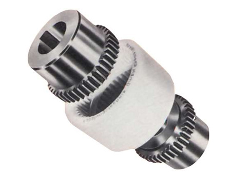
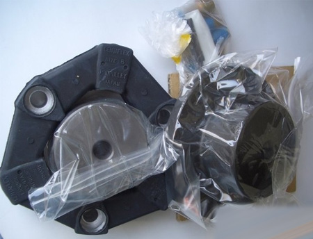
Plum-shaped elastic coupling
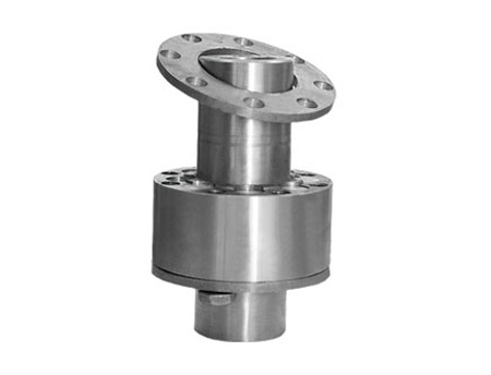
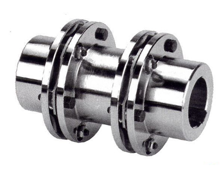
Diaphragm coupling
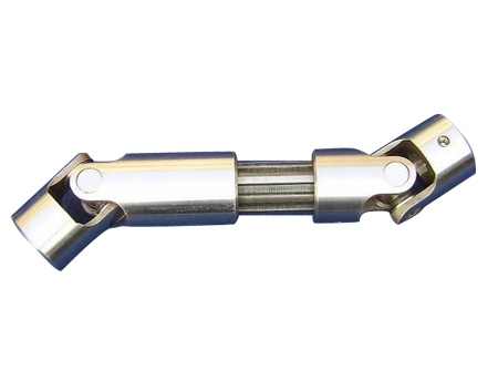
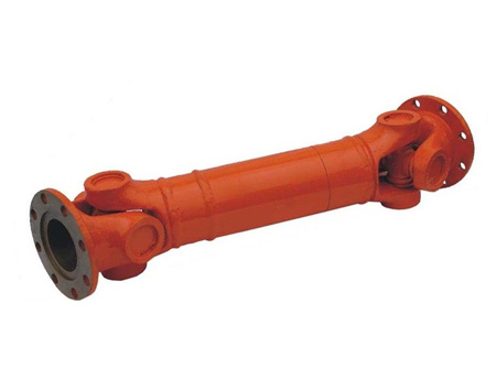
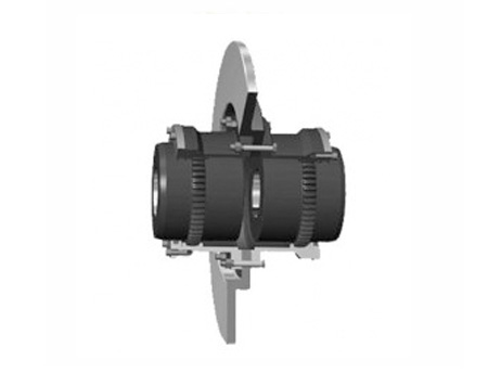
Universal coupling
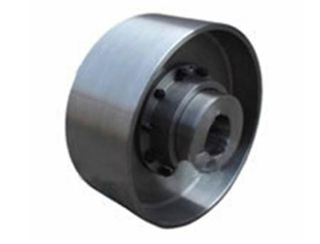
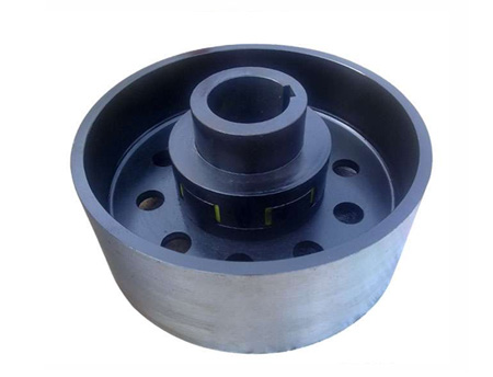
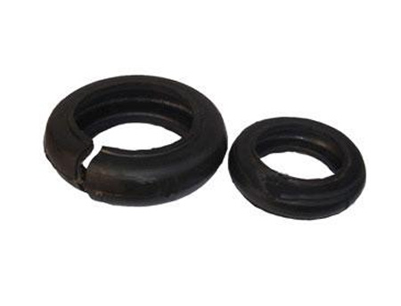
Tyre coupling
Slider coupling
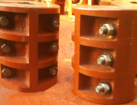
Rigid coupling
Star-shaped (shaped) elastic coupling
Drum gear coupling
Elastic sleeve pin coupling
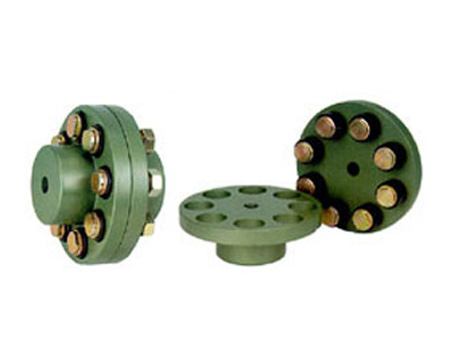
Elastic pin coupling
Elastic pin gear coupling
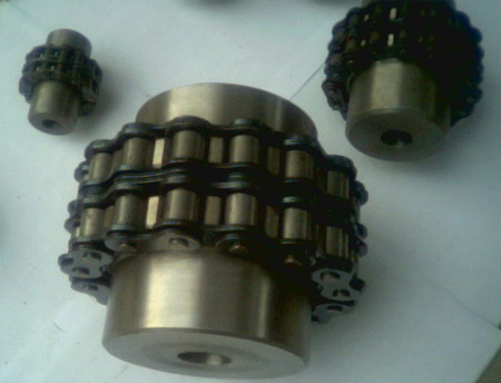
Roller chain coupling
Various coupling accessories
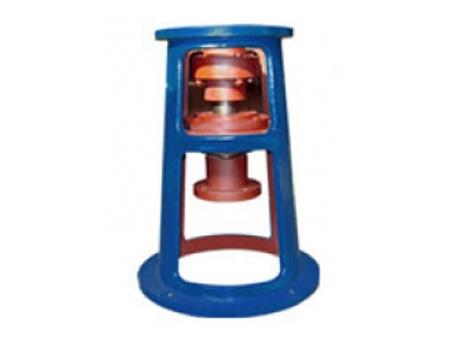
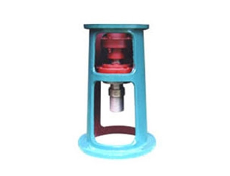
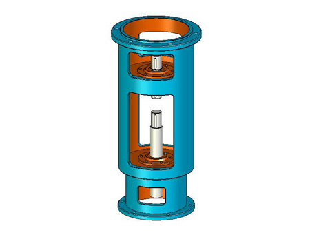
Water pump coupling
Expansion sleeve
Rack series
Website: www.rigid-shaft-coupling.xyz
Address: Xihuan Industrial Zone, Botou City, Hebei Province
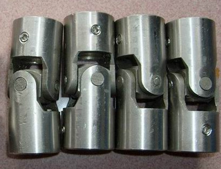
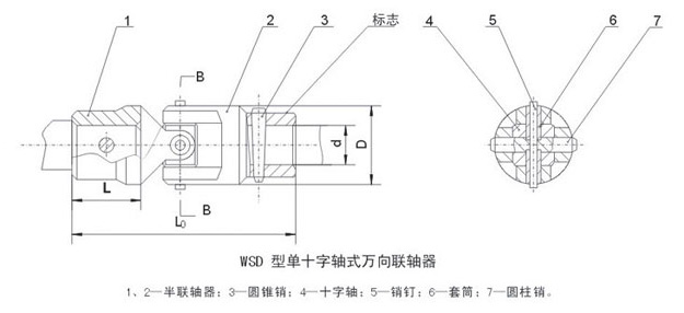
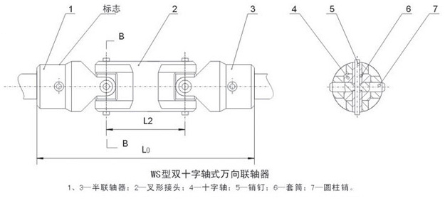
WS type WSD type cross universal coupling
The two shafts connected by the universal joint are deformed due to manufacturing errors, installation errors, shaft load, base deformation, bearing wear, temperature changes (thermal expansion, cold contraction), relative movement between components, etc. This kind of factor produces relative displacement.Under normal circumstances, the relative displacement of the two shafts is unavoidable, but the direction of displacement generated by the shafting transmission under different working conditions, namely axial (x), radial (y), angular (a) and displacement The size varies.
Basic parameters and main dimensions of WSWSD cross shaft universal coupling
|
model |
Rotation diameter |
Nominal torque |
Diameter of shaft hole |
L0 |
L |
L1 |
质量 |
Moment of inertia kg·M2 |
||||||||||
|
WSD type |
WS type |
|||||||||||||||||
|
Y type |
J1 type |
Y type |
J1 type |
Y type |
J1 type |
WSD type |
WS type |
WSD type |
WS type |
|||||||||
|
WS1WSD1 |
16 |
11.2 |
8 |
60 |
— |
80 |
— |
20 |
— |
20 |
Y type |
J1 type |
Y type |
J1 type |
Y type |
J1 type |
Y type |
J1 type |
|
9 |
0.23 |
— |
0.32 |
— |
0.06 |
— |
0.08 |
— |
||||||||||
|
10 |
66 |
60 |
86 |
80 |
25 |
22 |
0.20 |
0.29 |
0.05 |
0.07 |
||||||||
|
WS2WSD2 |
20 |
22.4 |
10 |
70 |
64 |
96 |
90 |
26 |
0.64 |
0.57 |
0.93 |
0.88 |
0.10 |
0.09 |
0.15 |
0.15 |
||
|
11 |
||||||||||||||||||
|
12 |
84 |
74 |
110 |
100 |
32 |
27 |
||||||||||||
|
WS3WSD3 |
25 |
45 |
12 |
90 |
80 |
122 |
112 |
32 |
1.45 |
1.30 |
2.1 |
1.95 |
0.17 |
0.15 |
0.24 |
0.22 |
||
|
14 |
||||||||||||||||||
|
WS4WSD4 |
32 |
71 |
16 |
116 |
82 |
154 |
130 |
42 |
30 |
38 |
5.92 |
4.86 |
8.56 |
0.48 |
0.39 |
0.32 |
0.56 |
0.49 |
|
18 |
||||||||||||||||||
|
WS4WSD4 |
40 |
140 |
19 |
144 |
116 |
192 |
164 |
48 |
16.3 |
12.9 |
24 |
20.6 |
0.72 |
0.59 |
1.04 |
0.91 |
||
|
20 |
52 |
38 |
||||||||||||||||
|
22 |
||||||||||||||||||
|
WS4WSD4 |
50 |
280 |
24 |
152 |
124 |
210 |
182 |
58 |
45.7 |
36.7 |
68.9 |
59.7 |
1.28 |
1.03 |
1.89 |
1.64 |
||
|
25 |
172 |
136 |
230 |
194 |
62 |
44 |
||||||||||||
|
28 |
||||||||||||||||||
|
WS5WSD5 |
60 |
560 |
30 |
226 |
182 |
296 |
252 |
82 |
60 |
70 |
148 |
117 |
207 |
177 |
2.82 |
2.31 |
3.90 |
3.38 |
|
32 |
||||||||||||||||||
|
35 |
||||||||||||||||||
|
WS6WSD6 |
75 |
1120 |
38 |
240 |
196 |
332 |
288 |
92 |
396 |
338 |
585 |
525 |
5.03 |
4.41 |
7.25 |
6.63 |
||
|
40 |
300 |
244 |
392 |
336 |
112 |
84 |
||||||||||||
|
42 |
||||||||||||||||||
|
Note: 1. The coupling mass and moment of inertia in the table are approximate values. |
||||||||||||||||||